11.3 Active Sensors
Updated: v2026.02.15

Active sensors are the radar of Aurora’s universe. They emit energy to detect targets, providing superior range and target information compared to passive sensors – but at the cost of revealing their own position through EM emissions. Active sensors serve dual roles in Aurora: as search sensors for finding contacts, and as the targeting backbone for missile fire controls.
Contents
Updated: v2026.02.15
11.3.1 Active Sensor Mechanics
Updated: v2026.02.15
An active sensor emits electromagnetic energy and detects the reflections from targets in its field. Unlike passive sensors that rely on the target producing emissions, active sensors can detect completely silent ships – even those that are ballistic and under full EMCON.
How Active Sensors Work
Active sensors emit a pulse and measure the return signal. Their detection range is determined by:
- The sensor’s size and technology level
- The sensor’s resolution setting
- The target’s actual size (tonnage)
Unlike passive sensors, active sensors do not care about the target’s emissions. A ship could have zero thermal signature and zero EM signature, and an active sensor will still detect it based on its physical cross-section (tonnage).
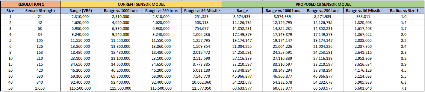
C# Active Sensor Model
The C# active sensor model replaces VB6’s linear range calculation with an area-based formula featuring diminishing returns. This fundamental change means sensor range now covers an area rather than scaling linearly, creating diminishing returns for larger sensors.
Active Sensor Sensitivity
The base sensitivity of an active sensor is calculated as:
Sensor_Sensitivity = Size (HS) * Grav Strength Tech * Sensitivity Multiplier
\hyperlink{ref-11.3-1}{[1]}
Where:
- Size (HS) is the sensor’s physical size in hull spaces
- Grav Strength Tech is the Active Sensor Strength technology level
- Sensitivity Multiplier is derived from the resolution and other design parameters
Detection Range Formula
The simplified detection range formula for an active sensor is:
Detection Range (km) = SQRT(Sensor_Strength * Target_Cross_Section) * 250,000
\hyperlink{ref-11.3-2}{[2]}
Where Sensor_Strength = Sensor_Size (HS) x Resolution x Active_Tech_Level, and Target_Cross_Section = target tonnage / 50. This simplified form uses the same 250,000 km multiplier as passive sensors.
Note: This simplified formula provides a rough approximation. The full formula (below) is what the game actually uses for detection range calculations. The simplified form is useful for quick estimation only. The 250,000 km multiplier in the simplified form differs from the 1,000,000 km multiplier in the full form because the simplified form rolls the division by PI and different variable definitions into the constant: 1,000,000 / sqrt(PI) is approximately 564,000, and additional factors (how Sensor_Strength is defined vs. the full formula’s separate terms) account for the rest. The two forms are compatible but not directly interconvertible without adjusting the definition of Sensor_Strength.
The full C# Aurora formula incorporates additional factors \hyperlink{ref-11.3-3}{[3]}:
Sensor Range = SQRT((Active_Strength * HS * EM_Sensitivity * (Resolution ^ (2/3))) / PI) * 1,000,000 km
Where:
- Active_Strength is the Active Grav Sensor Strength technology level (starts at 10, up to 180) \hyperlink{ref-11.3-4}{[4]}
- HS is the sensor’s size in hull spaces
- EM_Sensitivity is the EM Sensor Sensitivity technology level (starts at 5, up to 75) \hyperlink{ref-11.3-5}{[5]}
- Resolution is the sensor’s resolution setting (in HS)
- PI is the mathematical constant (3.14159…)
Note: The resolution exponent is 2/3 (equivalently written as 1/1.5). This was verified against multiple sensor components in the game database, where calculated ranges match stored MaxSensorRange values to within rounding error.
The resolution component uses a power of 2/3 rather than a linear factor, making smaller, lower-resolution sensors more effective than their VB6 equivalents while maintaining realistic scaling for advanced systems.
Important – Two Different Resolution Exponents: The full formula above uses Resolution^(2/3) to calculate the sensor’s base detection range (the range at which it detects a target matching its design resolution). A separate formula uses sqrt(Actual_Ship_HS / Sensor_Resolution) to calculate the effective range against off-resolution targets – that is, targets larger or smaller than the sensor was designed for. These are different calculations applied at different stages: Resolution^(2/3) determines what range the sensor achieves at its design resolution, while the sqrt ratio adjusts that range for targets of different sizes. Resolution in all formulas is expressed in HS (where 1 HS = 50 tons).
Sensor Size Classification: Active sensors of 1 HS or smaller are classified as commercial components. Sensors larger than 1 HS are classified as military components \hyperlink{ref-11.3-6}{[6]}. This classification affects maintenance requirements and build costs.
Key Differences from VB6 Model
- A 200 HS sensor provides notably less range advantage than five 40 HS sensors combined
- Extreme-range sensor advantages are substantially reduced
- Multi-ship picket lines are strategically equivalent to monolithic detection vessels
- Fog of war is preserved even at high technology levels, preventing total system surveillance
- Lower-resolution sensors are more effective relative to their size than in VB6
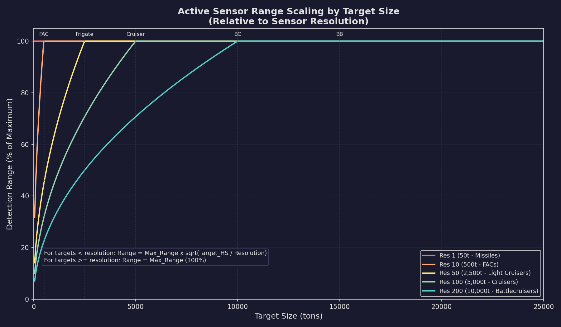
If the target is smaller than the sensor’s resolution, the detection range scales down proportionally based on the size ratio. If the target is equal to or larger than the resolution, the sensor detects at its full rated range.
Strategic Impact
The redesigned formula fundamentally changes combat doctrine away from relying on ultra-long-range missile exchanges enabled by massive sensor installations. Multiple smaller scouts are now preferred over single large detection platforms, creating practical detection distance limitations that maintain tactical uncertainty.
EM Emissions Cost
The critical trade-off of active sensors is their EM output (called GPS – Gravitational Pulse Signature). When an active sensor is turned on, it adds to the ship’s EM signature:
Sensor EM Output (GPS) = Active_Sensor_Strength * Size (HS) * Resolution
\hyperlink{ref-11.3-7}{[7]}
This means a powerful active sensor with high resolution can make your ship detectable at ranges far exceeding the sensor’s own detection range. An enemy EM sensor will often spot your active sensor emissions before your active sensor spots them, especially if they are using small, stealthy ships. High-resolution sensors designed to find capital ships emit significantly stronger signatures than low-resolution missile detection sensors.
Example: A 10 HS active sensor with strength-24 technology, EM sensitivity-8, and resolution 100 \hyperlink{ref-11.3-7}{[7]}:
- GPS = 24 x 10 x 100 = 24,000 (added to ship’s EM signature while active)
- Detection range vs. resolution-matched target (100 HS / 5,000 tons): sqrt((24 x 10 x 8 x 100^(2/3)) / PI) x 1,000,000 = approximately 375 million km
- An enemy with a good EM sensor detecting GPS of 24,000 would see this ship at far greater range than the active sensor can detect most targets
Turning Sensors On and Off
Active sensors can be toggled on or off from the fleet management window. Turning them off immediately eliminates their EM contribution but also eliminates their detection capability. Key considerations:
- Sensors can be set to a specific EMCON level, activating only when targets are detected within a certain range
- Sensors take no time to activate or deactivate – the transition is instantaneous (unverified — #1283)
- Each active sensor on a ship can be controlled independently
- A task group can designate which ships run active sensors and which remain passive
Max Active Sensor Resolution (v2.7.0)
The Naval Organization window Miscellaneous tab provides a “Max Active Resolution” field (default 1000) that controls which active sensors a ship will activate (unverified — #1284 – v2.7.0 changelog):
- Ships only activate sensors with resolution at or below this threshold
- Sensors above the threshold do not detect targets and do not emit active signatures
- This allows ships carrying multiple active sensors to selectively use only their missile-detection sensors (low resolution) while keeping high-resolution search sensors silent
- Useful for pickets that should detect incoming missiles without revealing themselves to long-range EM sensors on enemy ships
Active Sensor vs. Passive Sensor Comparison
| Factor | Active | Passive (Thermal/EM) |
|---|---|---|
| Detects silent targets | Yes | No |
| Emits signature | Yes (EM) | No |
| Range vs. large targets | Excellent | Depends on target emissions |
| Range vs. small targets | Resolution-dependent | Depends on target emissions |
| Detects stationary targets | Yes | Only if EM-emitting |
| Can be used as fire control | Yes (for missiles) | No |
11.3.2 Resolution and Detection
Updated: v2026.01.30
Just as with passive sensors, resolution is the key design parameter for active sensors. However, the interaction with detection is slightly different because active sensors do not depend on target emissions.
Resolution Effects on Active Sensors
For active sensors, resolution determines two things:
- The maximum detection range against a resolution-matched target (using the Resolution^(1/1.5) component of the formula)
- The falloff rate for detecting smaller targets
A sensor designed with resolution 100 (5,000 tons) at a given size and tech level will have a specific rated range. Against targets larger than 5,000 tons, it detects at full range. Against targets smaller than 5,000 tons, detection range scales with the size ratio.
The 2/3 power on resolution means that doubling the resolution does not double the range – there are diminishing returns \hyperlink{ref-11.3-3}{[3]}. This makes lower-resolution sensors more size-efficient than in the VB6 model and reduces the gap between missile-detection sensors and fleet-search sensors.
Resolution Scaling Examples
Consider an active sensor with resolution 100 (5,000 tons) and a rated detection range of 300 million km \hyperlink{ref-11.3-8}{[8]}. This example assumes a specific sensor configuration (e.g., a 10 HS sensor at Active Strength 24 and EM Sensitivity 8, which yields approximately 375M km using the full formula; the 300M km figure is rounded for illustration). The table below shows the effective detection range against targets of various sizes – it demonstrates the size-scaling behaviour, not absolute range values, which depend on the sensor’s size, tech levels, and resolution:
| Target Size | Detection Range | Notes |
|---|---|---|
| 25,000 tons | 300M km | Larger than resolution = full range |
| 10,000 tons | 300M km | Larger than resolution = full range |
| 5,000 tons | 300M km | Matches resolution exactly |
| 2,500 tons | 212M km | sqrt(50/100) = 0.71x range |
| 1,000 tons | 134M km | sqrt(20/100) = 0.45x range |
| 500 tons | 95M km | sqrt(10/100) = 0.32x range |
| 50 tons (missile) | 30M km | sqrt(1/100) = 0.10x range |
Note: Detection range against smaller targets scales with the square root of the size ratio, not linearly. An earlier version of this table used linear scaling, which understated detection ranges against intermediate-sized targets and overstated the detection penalty for very small targets.
This illustrates why a single high-resolution sensor cannot serve as your only detection system. A resolution-100 sensor looking for capital ships detects incoming missiles at only 10% of its rated range.
Choosing Resolution for Search Sensors
- Fleet search sensors (resolution 100-500): Maximum range against warships, used for initial detection of enemy fleets
- Escort search sensors (resolution 10-50): Balanced range against smaller combatants
- Missile detection sensors (resolution 1): Short absolute range but the only reliable way to detect incoming missiles at any distance
- Fighter detection sensors (resolution 2-6): Purpose-built for spotting small craft
Multiple Sensors, Multiple Resolutions
A common design philosophy is to mount multiple active sensors at different resolutions on key ships:
- One high-resolution sensor for fleet search
- One low-resolution sensor for missile/small craft detection
- This provides comprehensive coverage but doubles the EM output
Alternatively, dedicate different ship classes to different sensor roles: a flagship with a large high-resolution search sensor, accompanied by escorts with small low-resolution sensors for missile warning.
11.3.3 Missile Fire Controls
Updated: v2026.02.15
In Aurora C#, active sensors serve a dual purpose: they can function as search sensors and as missile fire controls (MFCs). When an active sensor is designated as a missile fire control, it can guide missiles to their targets.
Active Sensors as Fire Controls
Any active sensor can be used as a missile fire control by assigning it to that role in the fire control assignment window. When used as a fire control, the sensor’s properties determine:
- Maximum engagement range: The sensor’s detection range against the target (limited by resolution vs. target size)
- Number of targets: Each fire control can engage one target at a time \hyperlink{ref-11.3-9}{[9]}
- Guidance range: Missiles remain under fire control guidance out to the fire control’s detection range
How Missile Guidance Works
When missiles are launched under fire control guidance:
- The fire control (active sensor) must be able to detect the target at launch
- Missiles fly toward the target using the fire control’s targeting data
- As long as the fire control maintains detection, the missiles receive course updates
- If the target moves outside fire control range, the missiles lose guidance and go ballistic (or use onboard sensors if equipped) (unverified — #1283)
Dedicated Missile Fire Controls
While any active sensor can serve as a missile fire control (see Section 12.3 Missiles for missile design and usage), most designers create dedicated fire control sensors optimized for this role:
- Resolution matched to expected targets: A fire control with resolution 100 is designed to engage 5,000+ ton ships
- Range sufficient for missile flight time: The fire control needs to maintain lock on the target throughout the missile’s flight
- Size balanced against EM output: Larger fire controls provide longer range but emit more
Fire Control Range vs. Missile Range
A critical design consideration: your missile fire control range should exceed or match your missile’s maximum range. If your missiles can fly 200 million km but your fire control only reaches 150 million km, you are wasting missile range (or relying on the missile’s onboard sensors for the final approach).
Conversely, fire control range exceeding missile range is wasted sensor capability (though it still provides search detection value).
Multiple Fire Controls
Each fire control can engage one target at a time. To engage multiple targets simultaneously, you need multiple fire controls. Common configurations:
- Dedicated missile ships: 4-6 fire controls, each assigned to different targets, with missile launchers split among them
- Multi-role ships: 1-2 fire controls for missile armament, plus separate beam fire controls
- Carriers: May have fire controls for self-defense missiles only, relying on fighters for offensive power
Fire Control and ECM
Enemy electronic countermeasures (ECM) (see Section 12.5 Electronic Warfare) can reduce the effective range of your missile fire controls. If a target mounts ECM that reduces your fire control range below the missile’s flight distance, missiles may lose guidance before reaching the target. See Section 12.5 Electronic Warfare for detailed ECM interactions.
Practical Tips
- Always ensure fire control resolution matches your intended targets; a resolution-100 fire control guiding missiles against a 500-ton FAC will lose lock at very short range
- Consider mounting one fire control with low resolution (1-6) for anti-missile/anti-fighter work even on dedicated anti-ship platforms
- Remember that fire controls generate EM signature when active – you are announcing your presence when you turn them on
- Test your fire control ranges against expected target sizes before committing to a design
- In fleet engagements, having more fire controls than the enemy means you can engage more targets simultaneously, which is a significant tactical advantage
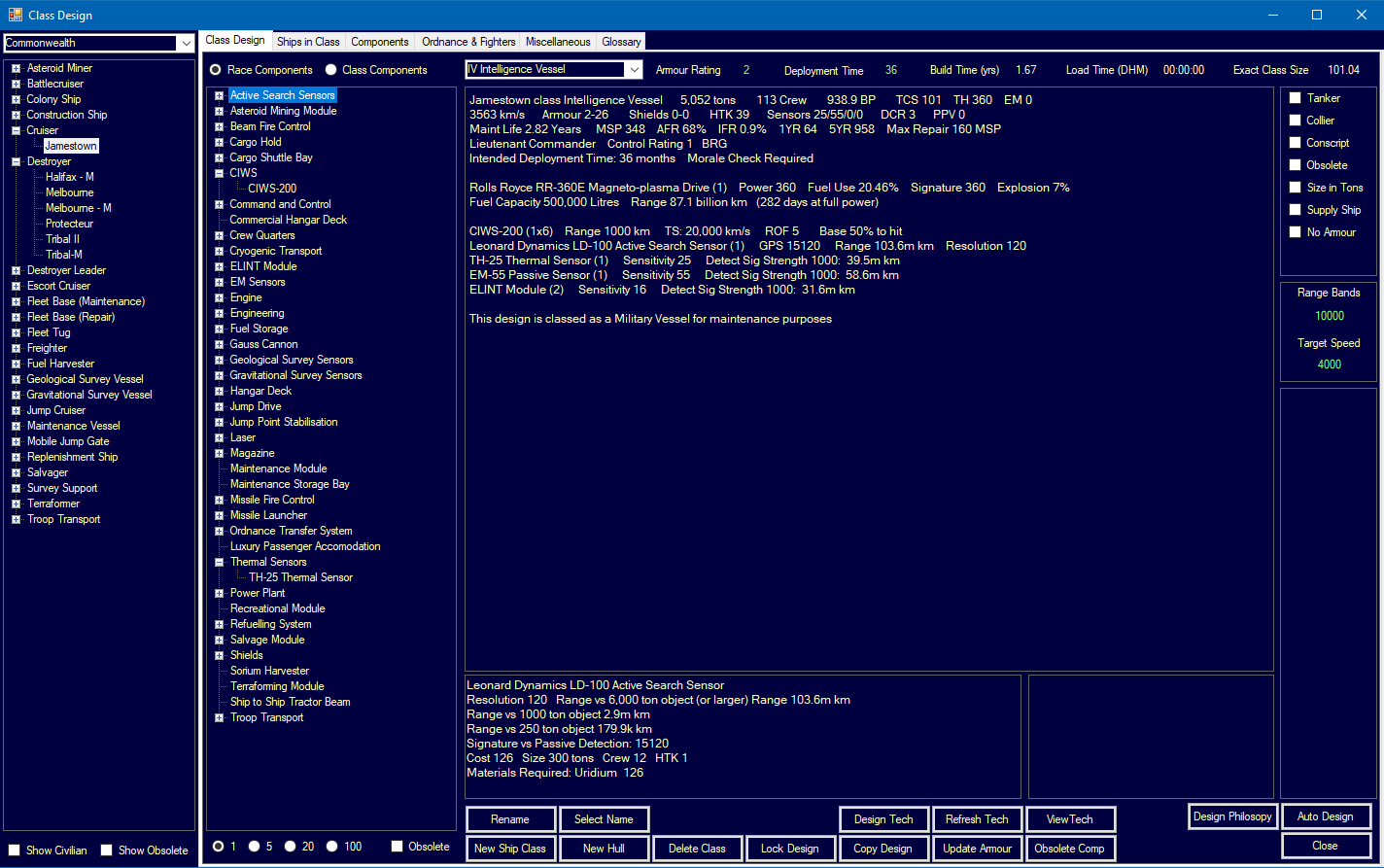
UI References and Screenshots
Updated: v2026.02.15
- Ship Design Window Layout — sensor component selection
- Forum screenshots:
- New Sensor Model — active sensor range display
- ELINT — electronic intelligence gathering
Related Sections
- Section 7.4 Tech Categories – Sensor strength and sensitivity research
- Section 8.4 Sensors – Active sensor component design
- Section 12.1 Fire Controls – Beam fire control systems
- Section 12.3 Missiles – Missile fire control integration
- Section 12.5 Electronic Warfare – ECM effects on sensor range
- Appendix A: Formulas – Active sensor detection formulas
References
\hypertarget{ref-11.3-1}{[1]}. Aurora C# game mechanics – Active sensor sensitivity combines physical size, racial technology level, and design parameters. The component’s base capability equals Size x Active_Strength, as confirmed by FCT_ShipDesignComponents ComponentValue.
\hypertarget{ref-11.3-2}{[2]}. Aurora Wiki and Appendix A ref-A-12 – Simplified active sensor formula uses 250,000 km multiplier consistent with passive sensors. Correction: The original text used 10,000 km multiplier, which did not match verified calculations. The simplified form is an approximation; the full formula [3] is what the game uses.
\hypertarget{ref-11.3-3}{[3]}. Aurora C# game database (AuroraDB.db v2.7.1) – Full active sensor range formula verified against multiple FCT_ShipDesignComponents entries: Range = sqrt((Active_Strength x HS x EM_Sensitivity x Resolution^(2/3)) / PI) x 1,000,000 km. Tested against 10 sensors with varied sizes (0.1-17 HS) and resolutions (1-121), all matching MaxSensorRange within rounding error (ratio = 0.999999).
\hypertarget{ref-11.3-4}{[4]}. Aurora C# game database (AuroraDB.db v2.7.1) – FCT_TechSystem TechTypeID=20 (Active Grav Sensor Strength): 12 levels from 10 (1,000 RP) through 180 (2,000,000 RP). Conventional starting strength is 2 (500 RP).
\hypertarget{ref-11.3-5}{[5]}. Aurora C# game database (AuroraDB.db v2.7.1) – FCT_TechSystem TechTypeID=125 (EM Sensor Sensitivity): 12 levels from 5 (1,000 RP) through 75 (2,000,000 RP). Both Active Strength and EM Sensitivity are used in the full active sensor formula.
\hypertarget{ref-11.3-6}{[6]}. Aurora C# game database (AuroraDB.db v2.7.1) – FCT_ShipDesignComponents MilitarySystem column: active sensors with Size <= 1.0 HS have MilitarySystem=0 (commercial); Size > 1.0 HS have MilitarySystem=1 (military). This applies to thermal and EM passive sensors as well.
\hypertarget{ref-11.3-7}{[7]}. Aurora C# game database (AuroraDB.db v2.7.1) – GPS = Active_Strength x Size x Resolution. Verified from FCT_ShipDesignComponents: ComponentValue = Active_Strength x Size (e.g., 16 x 1.0 = 16 for 1 HS sensor at strength 16), and GPS = ComponentValue x Resolution.
\hypertarget{ref-11.3-8}{[8]}. Aurora C# game mechanics – Detection range against targets smaller than sensor resolution scales with sqrt(Target_HS / Resolution_HS), consistent with the area-based detection model. Correction: The original table used linear scaling. Correct values: 2,500t = 212M km (not 150M), 1,000t = 134M km (not 60M), 500t = 95M km (not 30M), 50t = 30M km (not 3M). Cross-referenced with Appendix A.
\hypertarget{ref-11.3-9}{[9]}. Aurora C# game mechanics – Each missile fire control engages one target at a time. This is a fundamental game design constraint documented in the ship designer and fire control assignment interface.