8.4 Sensors
Updated: v2026.02.15

Sensors are your eyes and ears in space (see Section 11.1 Thermal and EM Signatures for detection mechanics). Without them, your fleet is blind — unable to detect approaching threats, find survey targets, or provide targeting data for weapons. Aurora C# models several distinct sensor types, each designed for a specific detection role. Understanding how they work and how to size them is critical for effective fleet design.
Contents
Updated: v2026.02.15
8.4.1 Thermal Sensors
Updated: v2026.02.15
Thermal sensors detect the heat signatures generated by ship engines. Every ship with engines running produces a thermal signature, making thermal sensors the most universally useful passive detection system.
How thermal detection works:
- Every engine produces a thermal signature proportional to its total engine power
- Ships with engines shut down have a minimum thermal signature based on hull size (crew generates heat)
- Thermal sensors detect engine thermal emissions at ranges determined by sensor sensitivity and target signature strength
- Thermal sensors also detect planetary thermal emissions from inhabited worlds, providing an alternative means of discovering alien civilizations alongside EM sensors
Sensor Size Classification:
All sensors (thermal, EM, and active) of 1 HS or smaller are classified as commercial components. Sensors larger than 1 HS are classified as military components \hyperlink{ref-8.4-3}{[3]}. This classification affects maintenance requirements, build costs, and which ship types can mount them without penalty.
Designing thermal sensors:
In the Component Design window, thermal sensors are configured with two main parameters:
- Sensitivity (rating): Higher sensitivity detects smaller signatures at greater range. Each point of sensitivity increases the detection range. Sensitivity is determined by the sensor technology level researched.
- Size (HS): Larger sensors have proportionally better range. A 10 HS thermal sensor detects targets at greater range than a 5 HS sensor of the same technology.
Detection range formula:
The detection range for thermal (and EM) sensors uses the following formula:
Detection Range (km) = SQRT(Sensor_Strength * Target_Signature) * 250,000
Where:
- Sensor_Strength = Sensor Size (HS) * Sensitivity Technology Level
- Target_Signature = The target’s thermal signature value (for thermal sensors) or EM signature value (for EM sensors)
The key relationships are:
- Range increases with the square root of the product of sensor strength and target signature
- Doubling sensor strength increases range by ~41% (square root of 2)
- Doubling target signature also increases range by ~41%
- Better technology provides higher base sensitivity multipliers
Thermal sensor technology progression:
The Sensors and Fire Control research category contains passive sensor strength technologies \hyperlink{ref-8.4-2}{[2]}. Each level increases the base sensitivity value, extending detection ranges.
Practical sizing:
- Scouts: 5-10 HS thermal sensors. These ships exist to find things — invest in sensor size.
- Warships: 1-3 HS thermal sensors. Enough for tactical awareness but not a primary role.
- Survey ships: 1-2 HS thermal sensors. Minimal — just enough to spot potential threats.
Thermal vs. EM: Ships always have a thermal signature when engines are running, making thermal sensors the more reliable detection method against ships in transit. EM sensors are better for detecting active sensor emissions, shield operations, and stationary targets using electronics.
Tip: Every combat fleet should include at least one ship with a large thermal sensor. This “eyes of the fleet” ship provides early warning and helps your battle group detect threats long before they reach weapon range. A 10 HS thermal sensor on a fast scout can give you hours of warning against approaching enemies.
8.4.2 EM Sensors
Updated: v2026.02.15
Electromagnetic (EM) sensors detect the EM emissions produced by active sensors, shields, and other electronics. While thermal sensors detect engines, EM sensors detect the electronic activity of ships — particularly those using active sensors or running shield generators.
What EM sensors detect:
EM sensors detect electromagnetic emissions from the following sources:
- Active sensor emissions from ships using radar/lidar (the biggest EM source)
- Shield generators when active (shield strength contributes to EM signature)
- Inhabited planets – populations generate detectable EM emissions proportional to their size and industrialization
- ECCM systems when active
A ship with no active sensors running and no shields has a minimal EM signature. This makes EM sensors situationally powerful – they excel at detecting ships that are actively scanning or fighting, but may miss a passive contact. EM sensors are also valuable for detecting inhabited worlds during exploration, providing early warning of alien civilizations.
Designing EM sensors:
EM sensors use the same design principles as thermal sensors:
- Sensitivity: Determined by research level. Higher sensitivity = better range.
- Size (HS): Larger sensors detect at greater range.
The detection range formula mirrors thermal sensors but uses EM signature instead of thermal signature.
Complementary to thermal:
The best sensor suites combine both thermal and EM sensors:
- Thermal sensors detect ships in transit (engines running) even if they are electronically quiet
- EM sensors detect ships that are stationary but electronically active (scanning, shields up)
- Together, they cover nearly all tactical situations
Resolution and identification:
Passive sensors (both thermal and EM) detect contacts but do not immediately identify them. A thermal contact shows up as “Thermal Contact - Speed XXXX km/s” with an estimated tonnage based on signature strength. You need active sensors or closer range to identify the contact as a specific ship class.
Tip: EM sensors are particularly valuable when facing enemies that use active sensors heavily. If an enemy fleet is scanning with powerful search radars, your EM sensors will detect them at extreme range — often before their own sensors detect you. This is a significant tactical advantage: you know they are coming, they do not know you are watching.
8.4.3 Active Sensors
Updated: v2026.01.30
Active sensors (radar/lidar) emit energy and detect the reflections. They provide precise targeting data, can determine ship class and composition, and are essential for missile fire control. However, they also broadcast your position to any passive EM sensor in range.
The active sensor trade-off:
Using active sensors is always a calculated risk:
- Benefit: Precise detection, identification, and targeting data
- Cost: Your ship’s EM signature spikes dramatically, making it visible to enemy passive sensors at potentially much greater range than your active sensor can detect them
This creates an asymmetric information problem. A ship with active sensors on can be detected by passive EM sensors at ranges far beyond what the active sensor can see. Experienced players often keep active sensors off until they have a reason to turn them on.
Designing active sensors:
Active sensors have more design parameters than passive sensors:
- Size (HS): Larger sensors have greater detection range. This is the primary range determinant. Sensors of 1 HS or smaller are classified as commercial; sensors larger than 1 HS are military \hyperlink{ref-8.4-3}{[3]}.
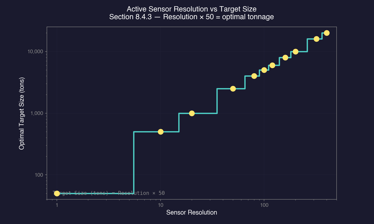
- Resolution: This determines what size of target the sensor is optimized to detect. A sensor with resolution 100 is optimized for 5,000-ton targets (resolution * 50 = optimal target size in tons) \hyperlink{ref-8.4-4}{[4]}. Targets larger than optimal are detected at proportionally greater range; smaller targets at reduced range.
- Technology level: Higher Active Sensor Strength technology increases base detection range \hyperlink{ref-8.4-1}{[1]}.
- Total range: Displayed in the designer, this is the maximum detection range against a target of optimal size.
Active sensor sensitivity formula:
The base sensitivity of an active sensor is determined by the Active Grav Sensor Strength technology \hyperlink{ref-8.4-1}{[1]}:
Active Sensor Sensitivity = Size (HS) * Active Grav Sensor Strength Tech
The detection range against a target uses:
Detection Range (km) = SQRT(Sensor_Sensitivity * Target_Cross_Section) * 1,000,000
Where Target_Cross_Section is the target’s size in HS (tonnage / 50). This means active sensors detect targets based on physical size rather than emissions.
Resolution targeting:
Resolution is critical for sensor effectiveness:
- Resolution 1 (50 tons): Optimized for detecting missiles. Used on anti-missile fire controls and missile defense sensors. Detects larger ships too, but at the same range regardless of their size.
- Resolution 10-20 (500-1,000 tons): Good for detecting fighters and FACs.
- Resolution 80-120 (4,000-6,000 tons): General purpose. Detects destroyer-to-cruiser sized ships effectively.
- Resolution 160-200 (8,000-10,000 tons): Capital ship detection. Maximum range against large warships.
- Resolution 320+ (16,000+ tons): Specialized for detecting very large ships at extreme range.
Important: A sensor with resolution 100 detects a 5,000-ton ship at its maximum rated range. A 10,000-ton ship would be detected at approximately 141% of that range (square root of the size ratio). A 1,000-ton ship would be detected at approximately 45% of rated range.
Active sensor emissions:
When active, these sensors produce an EM signature equal to their total detection range value \hyperlink{ref-8.4-5}{[5]}. A sensor with 100 million km range produces an EM signature of 100. This means a ship with a 10 HS EM sensor could detect the active sensor’s emissions at far greater range than the active sensor can detect the passive ship.
Sensor modes:
Active sensors can be set to:
- Off: No emissions, no detection. The ship is passive-only.
- On: Full emissions, full detection capability.
Fleet commanders typically keep active sensors off during approach and only activate them when combat is imminent or when they need precise targeting data.
Designing for specific roles:
- Fleet search sensor: Large (10-20 HS), high resolution (100-200), mounted on flagships or dedicated sensor ships. Provides long-range detection of enemy warships.
- Missile defense sensor: Small-medium (3-5 HS), resolution 1, designed to spot incoming missiles. Essential for point defense operations.
- Fire control sensors: See Section 8.6 Other Components — these are specialized active sensors that provide targeting data to weapons.
Creating Active Sensors (Create Research Project Window):
Active sensors are designed through the Create Research Project window under Sensors and Control Systems. The design workflow:
- Select Category: Choose the active sensor type from the component list
- Set Target Size: Specify the target tonnage the sensor is optimized to detect (e.g., 5,000 tons, 4,000 tons). Adjusting target size changes detection distances for different ship classes
- Set Sensor Size (HS): Larger sensors provide greater range but cost more. Sensors of 1 HS or smaller are classified as commercial; sensors larger than 1 HS are military
- Review Range Values: The interface displays detection distances for various target sizes in a list, along with the sensor range formula for reference
- Name the Component: Assign a designation for the sensor
- Create or Prototype: Create adds it to the research queue (must be researched before use); Prototype makes it immediately available for design experimentation but cannot be built until researched
Warning: Some fields in the sensor design interface are directly editable text boxes. Resting a finger on a key can accidentally overwrite calculated values. Double-check values before confirming the design.
Early-game guidance: A basic active sensor with default parameters is sufficient for initial system protection. You do not need an optimized sensor design to begin defending your home system – focus on getting any active sensor operational, then refine designs as your technology improves.
Sensor networking: The active sensor providing targeting data does not have to be on the same ship that is firing. Any active sensor in range of both the firing ship and the target can communicate targeting data to weapons platforms across the task group.
Tip: Never put your best search sensor on a ship that operates alone. If that ship is destroyed, you lose your fleet’s eyes. Instead, put primary sensors on well-protected ships (or carry redundant sensor ships). Also consider that the ship with the active sensor is the one broadcasting its position — sometimes it is better to have a decoy ship run active sensors while your main fleet approaches passively.
8.4.4 Geological and Gravitational Sensors
Updated: v2026.01.30
Survey sensors are specialized instruments used to explore planets, moons, asteroids, and jump points. They have no combat application but are essential for expanding your empire.
Geological Survey Sensors:
Geological sensors scan planets, moons, asteroids, and comets for mineral deposits. Without geological survey data, you cannot know what resources a body contains or whether it is worth mining.
Warning: Geological survey sensors cause the ship to be classified as military regardless of what engine type is installed. This means survey ships require naval shipyards (not commercial) to build and incur military maintenance costs. Using a commercial engine on a survey ship is still beneficial – the engine itself is exempt from maintenance failures, reducing overall maintenance burden – but the ship classification remains military.
Design parameters:
- Size (HS): Larger sensors survey faster. A 50 HS geo sensor surveys much more quickly than a 5 HS sensor.
- Survey speed: Determined by sensor size and technology level. The survey points generated per time increment determine how quickly a body is fully surveyed.
Survey mechanics:
- Each body has a number of survey points required to complete a geological survey
- Your sensor generates points over time based on its size and the ship’s speed (for asteroids/comets that require orbital passes)
- Larger bodies (gas giants, large terrestrial planets) require more survey points
- Asteroids and comets in belts are surveyed individually, requiring the ship to move between them
Gravitational Survey Sensors:
Gravitational sensors detect jump points within a star system. Jump points are invisible until a gravitational survey locates them. Without grav survey ships, you cannot expand to new systems.
Design parameters:
- Size (HS): Like geo sensors, larger grav sensors survey faster.
- Survey speed: Larger sensors accumulate gravitational survey points more quickly.
Survey mechanics:
- Each system has a number of potential jump point locations
- The grav survey ship must traverse the system, accumulating survey points at each potential location
- When enough points are accumulated at a location, any jump point there is revealed
- Survey is complete when all potential locations have been checked (some systems have many jump points, others have few)
Combined survey ships:
You can install both geological and gravitational sensors on the same hull. This is common for early-game survey frigates — one ship can both find jump points and survey mineral deposits in new systems. However, specialized ships (one for geo, one for grav) survey faster since they can carry larger individual sensors.
Survey sensor sizing guidelines:
- Minimum viable: 5 HS sensor. Slow but functional. Appropriate for budget-constrained early games.
- Standard: 10-20 HS sensor. Reasonable survey speed for most situations.
- Fast survey: 30-50 HS sensor. Quickly surveys systems, allowing rapid expansion. Requires a larger hull to accommodate.
Tip: Your first survey ships should carry both sensor types (geo + grav) with at least 10 HS each. This gives you maximum flexibility early on — you can survey jump points and mineral deposits in the same mission. Later, when you have more industrial capacity, build dedicated grav survey ships (faster jump point detection) and dedicated geo survey ships (faster mineral scanning). The time savings add up enormously as your empire expands to dozens of systems.
Survey commander bonus:
Officers with the Survey bonus (see Section 16.3 Assignments) increase survey speed. Assign your best survey-skilled officers to your survey ships for meaningfully faster exploration. This bonus stacks with sensor size, so a good officer on a ship with large sensors surveys very quickly.
8.4.5 Sensor and Fire Control Range Coordination
Updated: v2026.01.30
Designing sensors, fire controls, and weapons in isolation is a common early-game mistake. These three systems form a detection-to-engagement chain, and a mismatch at any link means wasted tonnage, missed shots, or targets you can see but cannot hit.
The fundamental principle:
Your detection range, fire control range, and weapon range must be coordinated so that each system in the chain can hand off to the next without gaps. The ideal relationship is:
Active Sensor Range >= Missile Fire Control Range >= Missile Range
If any of these relationships are inverted, you have a design problem.
What happens when ranges are mismatched:
- MFC range < sensor range: You detect targets at extreme range but cannot lock onto them. Your sensor operator sees the enemy fleet approaching and your fire control officer shrugs — the lock-on system cannot reach that far. You have wasted tonnage on sensor capability you cannot exploit offensively.
- Sensor range < MFC range: Your fire control is theoretically capable of locking targets at ranges your sensors cannot detect. Without sensor data, fire controls have nothing to lock onto. The extra fire control range is dead weight.
- Missile range < MFC range: You can detect and lock a target, but your missiles run out of fuel before reaching it. You get a satisfying lock tone followed by missiles going ballistic short of the target. Embarrassing and wasteful.
The ideal coordination (missile ships):
Design your systems so that detection leads to lock-on leads to engagement in a smooth cascade:
- Active sensor detects the target at maximum range (earliest warning)
- Missile fire control can lock the target once it enters MFC range (which should be at or within sensor range)
- Missiles can reach the target once launched (missile range should be at or within MFC range)
A practical margin of 10-20% overlap between each stage accounts for target movement and engagement geometry. If your MFC range is exactly equal to your missile range, a target moving away from you at speed may escape the missile envelope despite a valid lock.
Example coordination:
Active Sensor Range:        180M km  (detects target)
Missile Fire Control Range: 160M km  (locks target)
Missile Range:              140M km  (engages target)
This gives you 20M km of early warning between detection and lock-on, and 20M km of margin between lock-on and engagement. At each stage, the next system in the chain is ready before it is needed.

For beam ships:
Beam weapons have much shorter ranges than missiles, so the coordination principle simplifies. Your active sensor range should comfortably exceed your beam weapon range so you detect threats well before they enter firing range. This gives you time to maneuver, choose engagement angles, and decide whether to fight or withdraw. A beam ship that detects enemies only at beam range has no tactical options — it is already committed to the fight.
Resolution matching:
Design your active sensor resolution to match the expected target size for maximum detection range. A sensor with resolution 100 (optimized for 5,000-ton targets) gives maximum range against 5,000-ton ships. If you expect to fight 10,000-ton battlecruisers, a resolution of 200 gives you better detection range against those specific targets. Mismatched resolution means your quoted sensor range is optimistic — you will detect actual targets at reduced distances.
This does not mean you need perfect resolution matching. Targets larger than your resolution are detected at greater-than-rated range (good). Targets smaller than your resolution are detected at reduced range (potentially dangerous). When in doubt, design for the smallest threat you need to detect at maximum range.
Sensor sharing within task groups:
Not every ship in a task group needs maximum sensors. Aurora allows sensor data sharing within a task group — any ship with an active sensor can provide targeting data to any other ship in the same group. This means you can concentrate your sensor investment on one or two ships and let the rest carry more weapons or defenses.
The practical implication: your missile destroyers do not each need a 15 HS search sensor. One ship in the group with a powerful sensor can feed targeting data to the entire fleet. The destroyers only need fire controls and weapons — the sensor ship handles detection.
The dedicated sensor ship concept:
Taking sensor sharing to its logical conclusion, many experienced players design a dedicated sensor ship — a hull optimized purely for detection. This ship carries oversized active sensors (and often large passive sensors too) and provides targeting data for the entire battle group.
Advantages of dedicated sensor ships:
- Concentrated investment: One 20 HS sensor on a dedicated hull outperforms five 4 HS sensors spread across combat ships (detection range scales with sensor size, not number of sensors)
- Design freedom: Combat ships freed from sensor requirements can carry more weapons, armor, or engines
- Redundancy through spares: Build two sensor ships and keep one in reserve. Losing a sensor ship is recoverable; losing sensors distributed across your whole fleet is not
- Tactical flexibility: The sensor ship can operate ahead of the main fleet as a picket, or behind it for protection
Disadvantages:
- Single point of failure: If the sensor ship is destroyed or disabled, the fleet goes blind until a replacement arrives (mitigate with backup sensor ships)
- Priority target: Enemy commanders will recognize and target your sensor ship. It needs protection or must stay at safe range
- EM beacon: A ship running powerful active sensors broadcasts its position to every passive EM sensor in range. The sensor ship is inherently the most visible ship in your fleet
Practical tip: For your first combat fleet, a simple rule works well — design your missile fire control range to match your best active sensor’s detection range against the expected target size, then design missiles with enough fuel to reach 80-90% of that range. This gives you a coherent engagement envelope without overcomplicating the design process. Refine the margins as you gain experience with actual combat ranges.
Related Sections
- Section 11.1 Thermal and EM Signatures – Detailed detection mechanics and ranges
- Section 7.4 Tech Categories – Sensors and Fire Control research category
- Section 8.5 Weapons – Fire controls that sensors feed targeting data to
- Section 8.6 Other Components – Fire control design parameters
- Section 17.1 Geological Survey – How survey sensors discover mineral deposits
- Section 16.3 Assignments – Officers with survey bonuses
- Appendix A: Formulas – Sensor range and detection calculations
References
\hypertarget{ref-8.4-1}{[1]}. AuroraDB.db FCT_TechSystem: Active Grav Sensor Strength (TechTypeID 20) – Conventional strength 2 through strength 180, 13 tiers
\hypertarget{ref-8.4-2}{[2]}. AuroraDB.db FCT_TechSystem: Thermal Sensor Sensitivity (TechTypeID 19) – Sensitivity 5 (1,000 RP) through 75 (2,000,000 RP), 12 tiers
\hypertarget{ref-8.4-3}{[3]}. AuroraDB.db FCT_ShipDesignComponents: Sensors at Size <= 1.0 HS have MilitarySystem=0 (commercial); sensors at Size > 1.0 HS have MilitarySystem=1 (military). Verified across Active Search Sensors, EM Sensors, and Thermal Sensors.
\hypertarget{ref-8.4-4}{[4]}. AuroraDB.db FCT_ShipDesignComponents: Active sensor resolution maps to optimal target size via resolution * 50 = tons (since 1 HS = 50 tons). E.g., Resolution 102 targets 5,100-ton ships (102 HS).
\hypertarget{ref-8.4-5}{[5]}. Aurora Forums — Active sensors produce EM signature equal to their maximum detection range value (in millions of km). Community-documented mechanic.